Due to many e-mail requests, I decided to implement this IR security system circuit with all the features such as alarm, relay activated switch/light, timer, regulated power unit and error correction circuit on a single PCB.
I can provide the PBC along with all the devices for a reasonable price. Interested parties, blog me. Please note that I’ll not reply for the email requests anymore starting from today.
Friday, June 27, 2008
Thursday, June 12, 2008
My First Activity

Fig.017a shows mounting arrangement for both the transmitter and receiver units on the gate pillars. To achieve a high directivity of the IR beam towards the sensor, use a reflector behind the IR LED.
After both the units have been built, connect 6V power supply to the transmitter and the receiver circuits.
The transmitter and receiver units are aligned such that the IR beam falls directly on the IR sensor. As long as IR beam falls on the sensor, its output remains low.
When anyone interrupts the IR beam falling on the sensor, its output goes high to drive transistor into conduction and pin 2 of NE555 goes low momentarily. As a result, NE555 gets triggered and its pin 3 goes high to drive the relay circuit. Output pin 3 of NE555 remains high for around 30 seconds.
Tuesday, June 10, 2008
Connecting a Relay
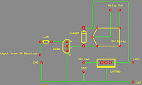
Here is the circuit diagram to connect a relay to the IR receiver end. Connect IR receiver's output to the 1.8K resistor. Use LM7806 regulator IC to get 6V for the IR transmitter and the receiver. You can connect any electronic/electrical appliance to the relay output and it works according to the receiver's output.
Subscribe to:
Posts (Atom)


